- HOME
- Machinery & Rolls Division
- Our machines explained
Plastics Processing LIne

Rubber Processing LIne

Rolls from Nippon Roll
The kind of roll used in Nippon Roll’s machines is a round, cylindrical object made of metal. To give you an easy image, you can think of it as a rolling pin used for flattening flour. So, what is this roll used for?
Rolls are used to stretch raw materials like rubber or resin into thin sheet-like products. It is similar to the image of using a rolling pin to flatten a lump of buckwheat flour to make soba noodles. There are several types of rolls, and the type of roll must be selected based on the content of the product being manufactured.
So, what kinds of options are there for these rolls?
・Types of Rolls
There are two main ways to categorize rolls. First, they can be divided by size. The size of the roll must be changed based on the content of the product being manufactured. This size refers to the total length and diameter of the roll.
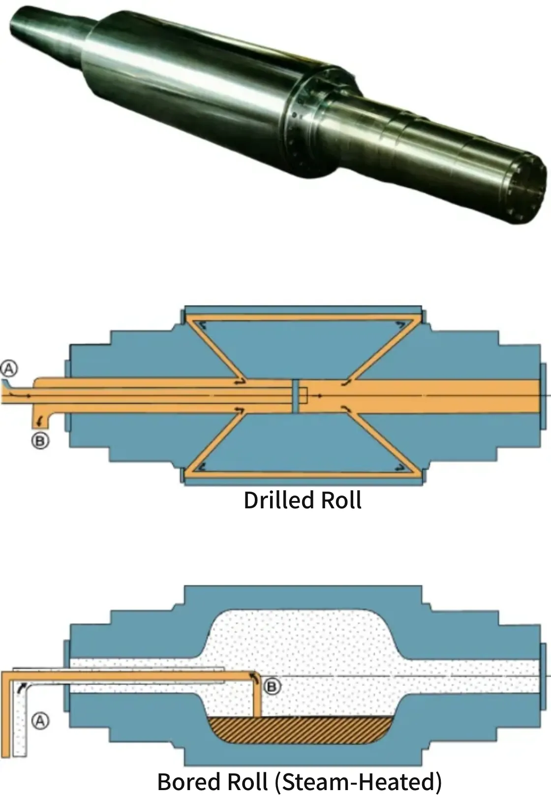
Next, the second way to categorize rolls is by internal structure. There are two types of internal structures: "bored" and "drilled." Nowadays, many companies have adopted "drilled" rolls. Furthermore, when further categorizing by purpose, considerations such as rigidity, wear resistance, ease of peeling off material, and surface roughness become necessary. However, the broad classification of rolls falls into these two categories.
However, unlike making noodles where you use a single rolling pin to flatten the dough on one surface, manufacturing products with rolls involves arranging multiple rolls in various configurations. Raw materials such as rubber or resin are passed between these rolls, gradually stretching them into the final product. The number and arrangement of these rolls must be adjusted depending on the type and purpose of the product being made.
Additionally, a machine is needed to rotate these rolls and stretch the materials. This machine, which rotates the rolls and passes the raw materials through them to extend them, is called a calender.
Calenders
In the plastics and rubber processing industry, a commonly used machine called a calender is a specialized piece of equipment designed for continuously rolling and shaping plastic or rubber materials. This machine typically consists of two or more temperature-controlled rolls that rotate in opposite directions. The raw plastic or rubber material is fed into the gap between these rolls, where it is flattened, smoothed, and formed into a continuous sheet or film of uniform thickness. Calenders are essential for producing a wide range of products, from thin films for packaging to thick sheets for automotive and industrial applications. The ability to precisely control the thickness and surface finish is crucial for ensuring the quality and consistency of the final product. Moreover, modern calenders often incorporate advanced control systems for greater accuracy and efficiency, adapting to the diverse requirements of the plastics and rubber industries.
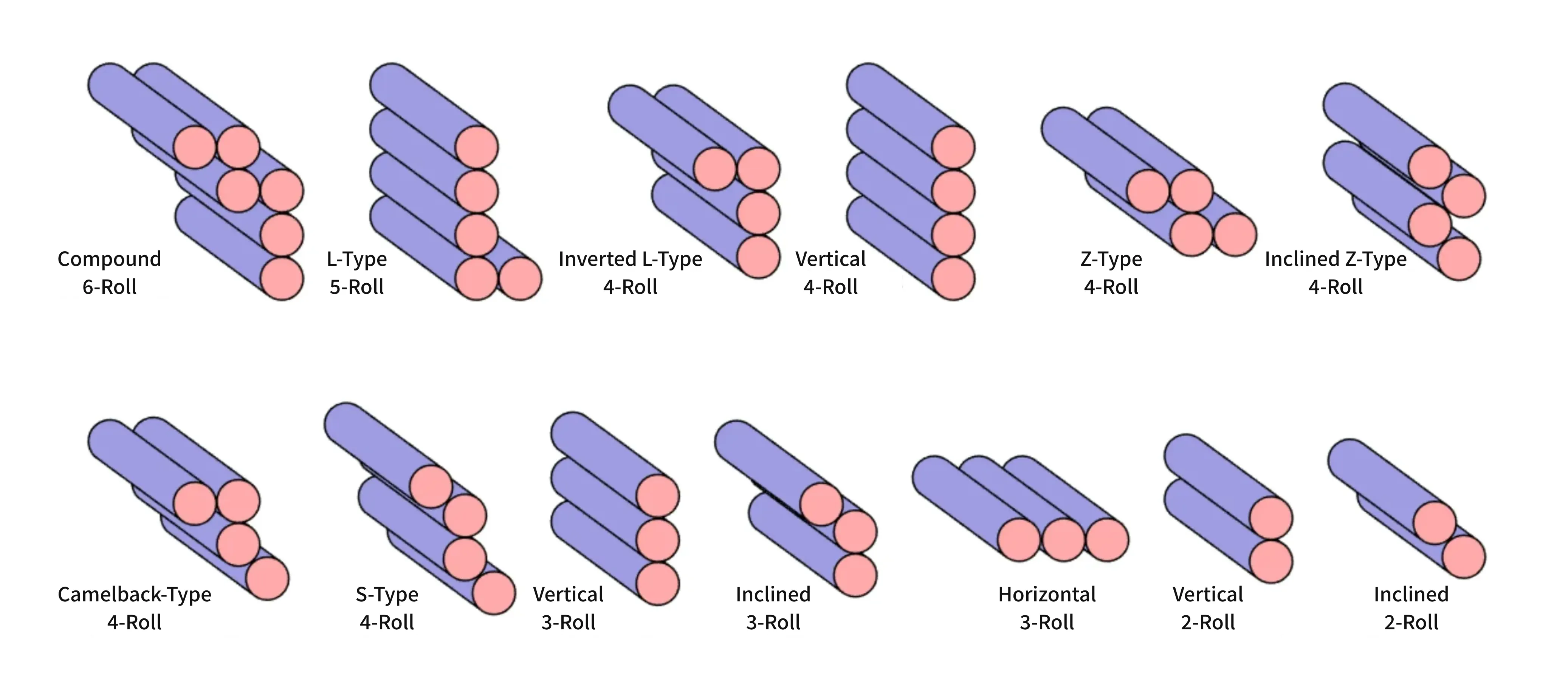
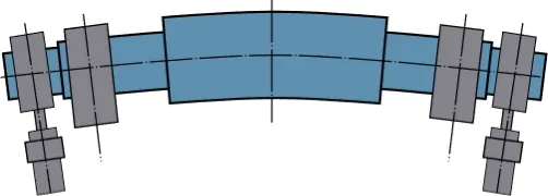
・Roll Arrangements
Calenders are designated by the size (diameter × working face length) and number of rolls used, as well as the type (arrangement of rolls). The rolls can be driven by various methods, such as universal drives and gear drives, but currently, most rolls are driven by universal drives.
For power, the individual drive system, which uses dedicated motors for each roll allowing the roll speed ratio to be freely set, has become common. We can modify your calender to an individual drive system, so please feel free to inquire about the feasibility.
We can also design other arrangements according to your needs.
・Overview of Calender Structure
Rolls
Calender rolls are manufactured using the highest quality chilled cast iron. The surface of the rolls is finished to a mirror polish, with roundness precision maintained to within a few microns at room temperature. The surface hardness is above 70º Shore (JIS). Internally, the rolls are machined to ensure uniform wall thickness and even temperature distribution.
- About Special Steel Forged Drilled Rolls
- Our company also supplies forged steel drilled rolls and recommends them for certain applications. Forged steel drilled rolls have a higher surface hardness compared to chilled cast iron rolls. Additionally, due to their superior rigidity, they can be longer relative to their diameter (L/D ratio of 3 to 4 times), which allows for smaller machinery even for wide-width products.
- Roll Crown
- When rolling between two rolls, a separating force acts between the rolls, causing them to bend and creating thickness variations in the product. To minimize this error, the roll surface is pre-polished into a curved shape. This process is called crowning, and the difference in diameter between the center and the ends of the roll is called the crown amount. This crown amount is determined for each roll based on its position in the arrangement and the rolling material conditions.
Friction Between Rolls
When adopting an individual drive system, where each roll is driven separately, the rotational ratio between each roll can be freely set. This addresses operational purposes (such as frictioning) and alleviates periodic error variations due to roll eccentricity. There is also a method to give rolls a rotational ratio using gears, which are housed within a pinion stand. This system can also be modified to an individual drive system.
Roll Bearings and Lubrication
Roll bearings use high-precision super-precision roller bearings, housed in specially cast iron housings. They are easy to maintain and can operate for long periods. Additionally, high-quality bronze plain bearings can be used upon customer request. Lubrication is provided by an independent oil tank, with oil being pumped to each bearing by a separate oil pump. The oil discharged from the bearings is returned to the tank through an inspection section. To prevent oil leakage, a labyrinth seal system is used to completely seal the oil, keeping the machine's surroundings clean.
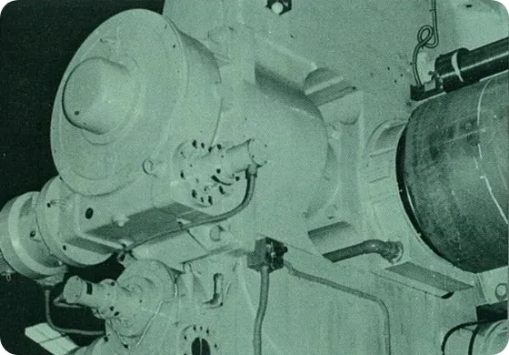
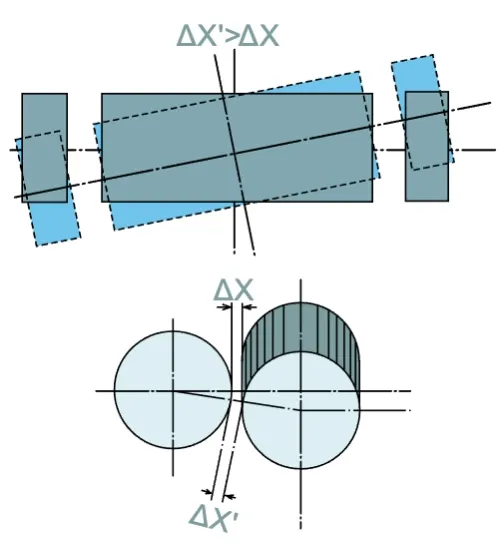
Roll Cross Device
This device corrects product precision errors due to roll deflection by crossing the rolls' axes. It is equipped on necessary rolls depending on the application. The roll bearing box is moved by a motor through a reduction gear and held in position by hydraulic or spring pressure. The amount of movement can be read on the control panel as the crown effect amount.
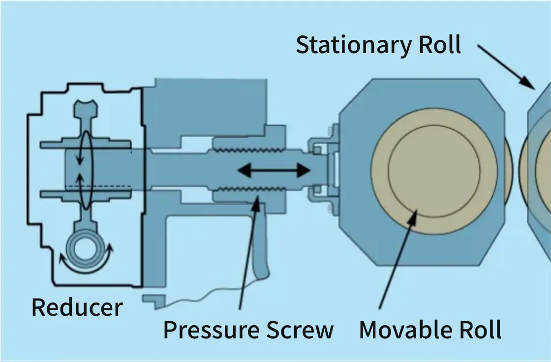
Roll Gap Adjustment
For one fixed roll, the other rolls have roll gap adjustment devices attached. The adjustment is made by rotating a push screw via a motor through a reduction gear, moving the roll bearing box, and correcting the product thickness. The movement is read by position sensors and displayed on the control panel.
Roll Bending Device
Similar to the pull-back device, a hydraulic bending device is installed at both ends of the roll shafts. By forcibly applying force outside both bearings to bend the roll, product precision errors are corrected.
Pull-Back Device (Zero Clearance Device)
A pull-back bearing is provided outside the main bearing, and the roll is pulled in the rolling load direction by a hydraulic cylinder or spring, eliminating play in the roll bearing and screw part, and following the movement of the main bearing quickly to stabilize product precision.
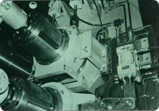
Universal Drive
Large calenders are typically driven via universal spindles that connect the rolls to the pinion stand. This universal drive system absorbs the core fluctuations arising from the required product thickness, ensuring smooth power transmission even at high speeds. The spindles use cross joints, ball joints, and flex-type gear couplings.
Emergency Braking Device
In an emergency, the rotation of the rolls can be stopped instantly by activating push buttons or contact bars on the machine side or control panel. Braking systems such as band brakes, electromagnetic brakes, dynamic brakes, and regenerative braking are employed.
Auxiliary Devices
Calenders also come with auxiliary devices like stock guides, edge cutters, press rolls, take-off devices, and guide rolls. These auxiliary devices are selected based on the application or working conditions.
Mixing Mills
Mixing mills have been used for rubber and plastic processing for a long time. They are mechanically simple, have few failures, and the work in progress can be inspected visually at any point.
Our mixing mills are designed and manufactured to withstand severe use, and we have delivered thousands of units to rubber and plastic-related companies, all of which have received high praise. Depending on the intended use, this machine is also called a sheeting mill or warming mill.
・Description of Main Parts
Rolls
The rolls are made of high-quality chilled cast iron. The surface of the rolls is polished, and the hardness is around 70º Shore (JIS). The interior is hollowed out for heating and cooling. Additionally, drilled rolls may be used to enhance kneading and mixing efficiency.
Roll Bearings and Lubrication
The bearings use either roller bearings or high-lead bronze plain bearings and are housed in specially cast iron bearing boxes. Lubrication systems are designed and manufactured to meet customer requirements, including forced circulation, forced lubrication, or grease lubrication.
Roll Gap Adjustment
The moving roll is equipped with a roll gap adjustment device, allowing the roll bearing box to move back and forth. The adjustment can be electric, performed by a motor through a reduction gear, or manual, also through a reduction gear. Ratchet handles can also be used for moving the adjustable roll. In the case of the electric type, the movement is read by a position sensor on the control panel. For the manual type, the reading can be done on a scale plate mounted on the front.
Roll Protection
To protect the rolls, frame, and other important parts from damage due to overload, a safety plate is installed between the gap adjustment push screw and the bearing box. If an overload occurs, this safety plate breaks, opening the roll gap and preventing damage to the rolls and frame. Hydraulic protection devices can also be provided depending on the application.
Reduction Gearbox
The reducer houses helical-type gears in a high-grade cast iron or welded steel casing, enabling quiet power transmission. All bearings are roller bearings, and lubrication for the gears and bearings is provided by an oil bath or forced lubrication system.
Bed
Nippon Roll’s mixing mills use common beds made of welded shaped steel, on which the main unit, reducer, and motor are all assembled. The common bed is supported and adjusted by leveling blocks. Depending on the application, a foundation type fixed with foundation bolts may also be used.
Emergency Braking Device
In an emergency, various switches installed around the machine can be activated to stop the rolls instantly. The types of braking devices and switch formats are designed, manufactured, and installed according to consultations.
Auxiliary Devices
Mixing mills come with auxiliary devices such as stock guides, blending devices, dividers, stock pans, and cutters. Stock guides can be fixed, hydraulically movable, or electrically movable, selected based on working conditions. Other attachments can be custom-designed to meet the needs of the client.
Intensive Mixers
Our intensive mixers are closed-type internal mixers of the Banbury type. Intensive mixers are designed to efficiently and economically pressurize and mix materials such as natural rubber, synthetic rubber, various resins, asphalt, cellulose, paint, and enamel. This machine is designed and manufactured with durability and wear resistance in mind to withstand all harsh operating conditions.
The mixing chamber is designed to circulate cooling water for rubber applications to suppress heat generation. For plastics and other materials, steam can be supplied for heating. The mixers are named according to the volume of the chamber, and the types are broadly classified into drop door types and slide door types based on the discharge method.
・Uses of Intensive Mixers
- 1.Mastication of natural rubber
- 2.Mixing various rubbers with carbon black (master batch)
- 3.Incorporating vulcanizing agents into rubber (final mixing)
- 4.Mixing various types of rubber
- 5.Mixing PVC (soft and rigid)
- 6.Mixing various types of plastics
- 7.Mixing flooring tiles (rubber, plastic, asbestos, asphalt, etc.)
- 8.Mixing various adhesives
- 9.Mixing various chemicals
・Features of Intensive Mixers
- 1.Can accommodate any shape as long as it fits in the input size. Suitable for a wide range of materials.
- 2.Superior mixing effects and high efficiency
- 3.Effective cooling and heating with temperature control
- 4.Maintains performance under harsh operating conditions
- 5.Long lifespan
- 6.Easy operation and safe to work with
Mixing in Intensive Mixers
Intensive mixers consist of four walls made of two mixer bodies and two metal bodies, with two rotors installed inside. The bottom is closed with a discharge door, and the top is pressurized and sealed with a floating weight. Mixing takes place within this sealed mixing chamber.
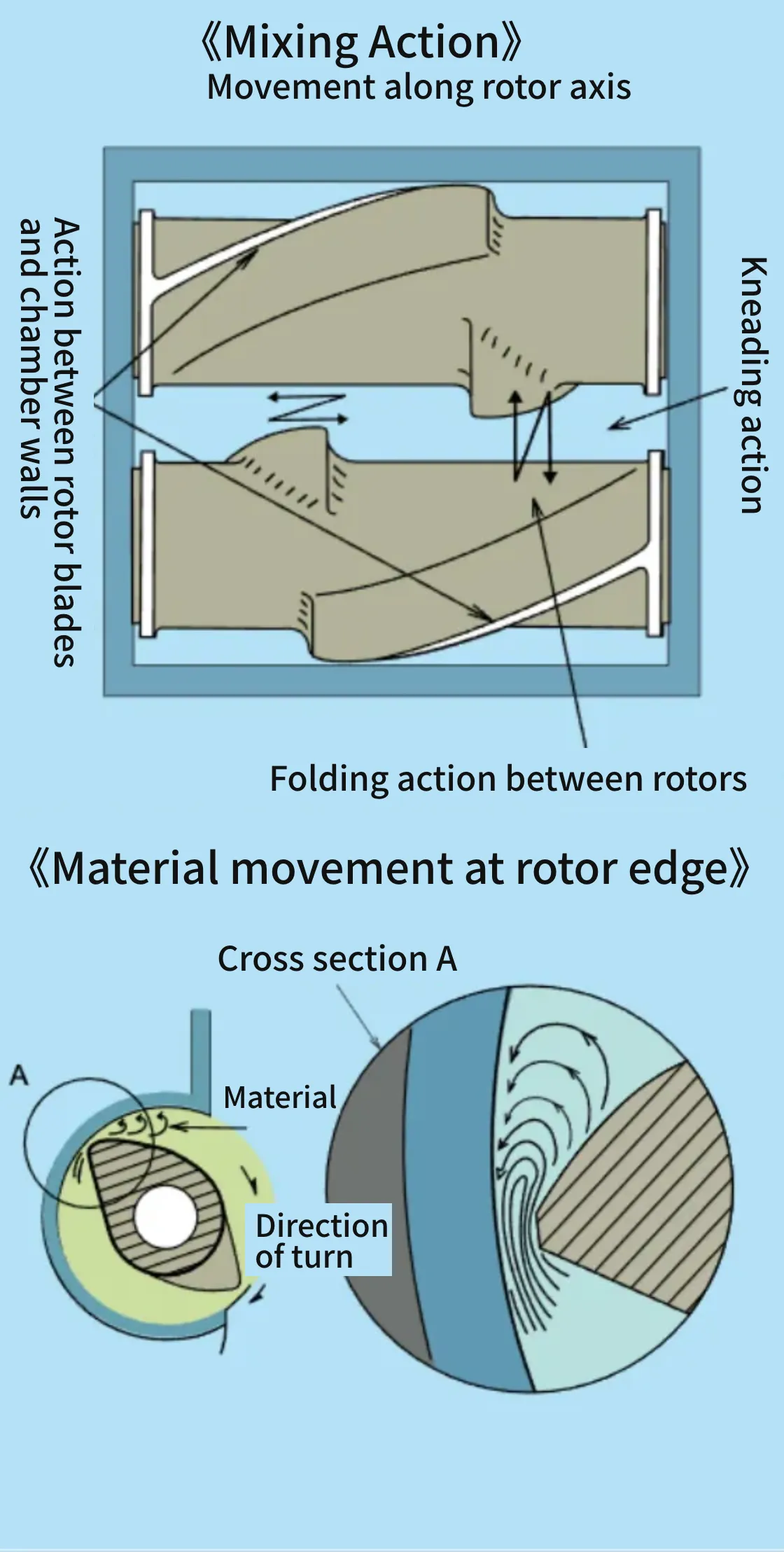
- 1.Mixing between the rotor blade tips and the mixer body inner walls
The material is mainly crushed between the rotor blade tips and the inner walls. The mixed material is first strongly torn apart and then crushed as it passes through the narrowest gap, before being released back into the rotation. - 2.Mixing by reversing direction along the rotor shaft
The rotor blades are twisted in a helical shape, continuously moving the material to the center of the chamber. Material near the blade surfaces is sequentially moved closer to the center for mixing. One rotor has blades twisted in the opposite direction of the other, with varying blade lengths. - 3.Mixing by overlapping of the two rotors
Material pushed by rotor A overlaps with material retained by rotor B, mixing together. Then, material pushed by rotor B overlaps with material retained by rotor A, continuing the mixing process. - 4.Mixing by kneading with the two rotors
Along with the effects mentioned above, the spacing and positions of the rotor surfaces continuously change due to the relative speed of rotation. This continuous change (kneading) results in thorough mixing of the material.
- Checking the Mixing State
- Since the chamber is sealed, the mixing state is judged by temperature and the power of the drive motor. The temperature of the material is detected and measured by a thermometer inserted into the mixing chamber.
・Overview of Intensive Mixer Structure
Drive System
The two rotors are each connected to the output shaft of the reducer via gear couplings. They are driven by the main motor through the reducer. Consequently, the gears that provide the rotational ratio to the two rotors are also incorporated within the reducer.
Rotors
The two rotors rotate at a fixed ratio to perform mixing. They are made of cast steel, and the blade sections have specially designed curves. The blade tips are hardened and improved for wear resistance through stellite welding. The rotor surface is finished with hard-chrome plating. The interior is hollow to allow for the circulation of cooling water, heating steam, or heat transfer oil.
Rotor Bearings and Lubrication
The Intensive Mixer uses roller bearings and they are housed in metal bodies. Lubrication is performed via forced circulation lubrication from a separate oil tank.
Mixing Chamber
The mixing chamber is composed of four walls made up of metal bodies and mixer bodies. The mixer bodies are hollow to allow the circulation of cooling water or steam. Specifically, for cooling, there are methods such as jet site, drilled site, and jacket types.
Powder Seal Device
Special devices are installed between the mixing chamber and rotor shafts to prevent leakage of the mixed material from the chamber. These devices include MS, DS, and RS types, which are chosen based on the mixed material and conditions.
Raw Material Feeding and Pressurization
Raw materials are fed into the hopper via conveyors, chutes, or manually. The hoppers are designed and manufactured in various types, including single-opening, double-opening, and those with side chutes for chemical addition. Once the raw materials are fed, the floating weight descends by the air cylinder from above, performing pressurization and mixing.
Discharge Device
After mixing is completed, the mixed material is discharged through the discharge door. Discharge devices are broadly classified into two types: slide door and drop door. The slide door type opens and closes by sliding the door using an air or hydraulic cylinder from below. The drop door type opens and closes by rotating the door using a rack and pinion mechanism or a rotary actuator driven by a hydraulic unit and hydraulic cylinder. The advantages of the drop door type are short opening and closing times, no material retention around the discharge, and complete prevention of leakage from the door.
Reducer
The reducer is a sealed casing that incorporates reduction gears and friction gears to provide the rotational ratio to the rotors. The gears use a single helical tooth design. All bearings are roller bearings, and lubrication is forced circulation lubrication along with the gears.
Control Panel
The control panel is usually mounted on the side of the feed opening. It includes air control valves, steam and water control valves, timers, pressure gauges, temperature indicators, ammeters, and other instruments. Depending on the requirements, standalone control panels with various operation buttons, recorders, and circuits can also be designed and manufactured. Recording items can include motor power, motor current, rotor speed, drop door temperature, inner chamber wall temperature, bearing temperature, powder seal part temperature, and heat medium supply temperature, among others, tailored to various requirements.
Strainers
Our strainers are primarily designed to remove lint, hair, iron filings, wood chips, and other contaminants that may be mixed into PVC resin and rubber during compounding and mixing. They perform continuous kneading and extrusion operations. The entire unit is compactly assembled on a common bed, making it easy to move and install.
・Description of Main Parts
Cylinder
The cylinder is made of welded steel plates, with a liner made of nitrided steel. The cylinder is divided into several zones, each of which can be temperature-controlled.
Screw
The screw is made of carbon steel and its surface is coated with hard-chrome plating. The interior is machined to allow the circulation of a temperature control medium. The spiral blade is designed for maximum efficiency.
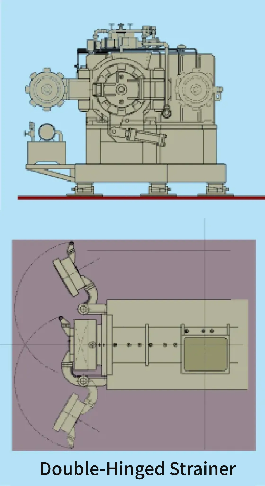
Head
The head features a double-hinge design and hydraulically clamped. Each hinge is fitted with a wire mesh screen that can be quickly replaced. The head is hollow, allowing for temperature control. After closing the head, it is clamped and fixed with a screw rotated by a hydraulic cylinder. Special types of heads can be designed and manufactured upon request.
Screw Bearings
To securely hold the screw, radial and thrust bearings are used. Lubrication can be either oil-bath or circulation type.
Reducer
The reducer houses helical gears in a cast iron or steel plate casing, enabling quiet power transmission. All bearings are roller bearings, and lubrication is provided by either oil cooling or forced lubrication systems.
Inquiries to the Machinery Roll Business Division
If you have any questions or inquiries about the Machinery Roll Business Division, please feel free to contact us.
- Inquiries via WebTo the Inquiry Form
- Inquiries by Phone03-3878-6661Reception hours / Weekdays 9:00 AM to 5:00 PM